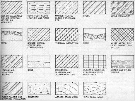
The surface cut by the cutting plane and exposed in the sectional view is indicated by drawing section lining on it. Section lining sympols may be used to indicate the type of material in the sectioned part. These sybols can only show the general type of materials (ie. plastic, wood, steel, glass, etc). They do not identify the specific material.
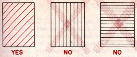
The section lines are normally drawn on a 45 degree angle. They must never parallel the edge of the surface (see below).
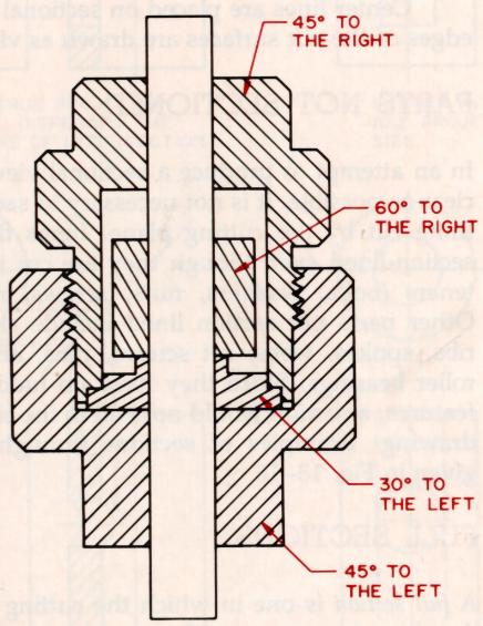
If a product has several parts, the section lining must be on a different angle for each part (see below).
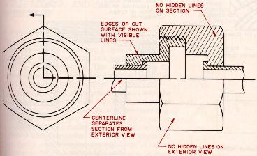
All visible edges and surfaces that can be seen behind the cut should be drawn. Since the section is drawn to clarify interior details, hidden lines are omitted (see below).
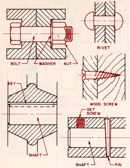
In an attemp to produce a sectional view that is as clear as possible, it is not necessary to section everything cut by the cutting plane. Examples of items not sectioned could include such things as bolts, washers, rivets, etc (see below).
Last Updated Jan. 31/00