
(Guided)
Create the following drawing and a layout using the dimensions provided.
Units - Decimal, Inches
Layout Scale - 1:1
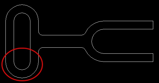
Finished Drawing

As stated previously, I will guide you through this first drawing. The method and steps I am about to demonstrate are by no means the only way to construct this drawing. The intent of this guided project is to help ease your transition into drawing using various geometric shapes. You do not need to use this help if you are comfortable in tackling this project on your own.
Start AutoCAD LT and create a new file with the following drafting settings.
Create an Object layer (default line and color values) and set the Object layer to active.
Set your snap settings to 0.25. You can leave the grid setting at the default 0.5. Turn your grid and snap on and then zoom in on the drawing area so that it is full screen.
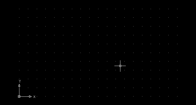
Where we start drawing is arbitrary. Generally you should look for a location that facilitates the placement of other objects on the drawing. Let's begin in the lower left corner of the drawing.
Move your origin somewhere inside the lower left corner of your drawing area. Use this origin to draw 2 circles with radius 0.5 and 1.0.
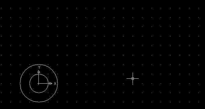
Note: Recall from the previous unit that the drawing area in most CAD applications is used to scale drawing objects and dimensions appropriately to the size of the drawing. It does not matter if your drawing fits neatly in the middle of your drawing area.
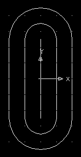
Next mirror the two circles so that a second set appears directly above the first set. The mirror line must be exactly 1.25 units above the origin.

Result

Next snap tangent lines connecting the circles. You can use the snap to tangent tool or in this case snap to quadrant will work as well.

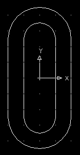
Next trim away the unwanted sections of circle. You may need to turn off your snap temporarily so that the circles can be selected.

Let's now construct the right portion of the drawing.
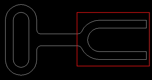
By extrapolation, we know that the center of the circular portion of this section is 5 units away from the centers of the other circles. If you have your grid set up appropriately, you can derive this location without having to build any construction lines to locate this point.
For demonstration purposes, I will demonstrate locating the exact location of the region indicated above using construction lines.
Snap a line from the center to center of the existing circles and then move your origin to the midpoint of the line (see below). After you've done that, you can delete the construction line.
 |
 |
From this reference point, you can draw your circles for the right section of the drawing or you could move your origin 5 units to the right and then draw the circles from the origin.
Locate and draw the two circles (radius 0.75 & 1.25).
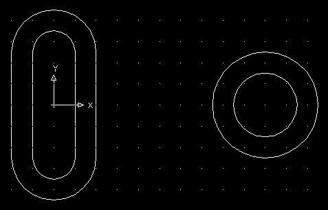
If you haven't done so already, locate the origin to the centers of the new circles.

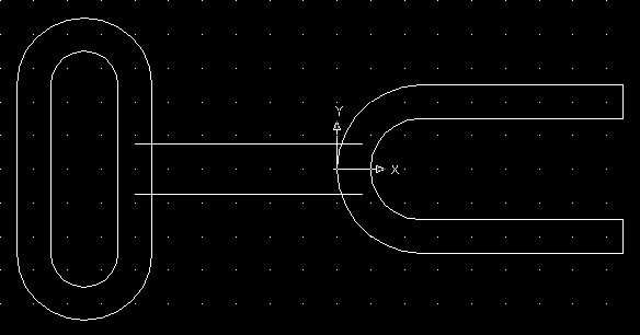
Next draw the following lines. If you have your snap settings set to 0.25, you should be able to draw the lines using your mouse and the current grid snap settings. An alternative would be to snap your origin to each quadrant and then draw lines 3 units long from each origin and then snap lines from endpoint to endpoint to connect the lines on the right sides.
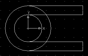
Next, trim away any unwanted lines.

Next, snap your origin to the following quadrant.

We now need to draw 2 lines (0.75 units apart) connecting both sections. There are several ways to do this. I will demonstrate 1 solution.
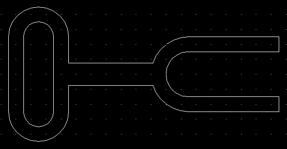
Change your snap settings to 0.375 (0.75 divided by 2).
Making sure your snap is turned on, draw 2 lines using your snap settings. The first line above your origin and the second line below your origin. Make sure your lines overlap the left and right sections.
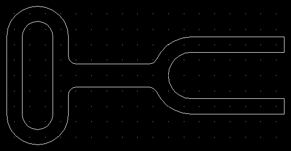
Next, trim the drawing as follows.
Next, fillet the 4 inside corners to a radius of 0.25 using the fillet tool.
Finally, create your Layout (Scale 1:1) and Title Block.
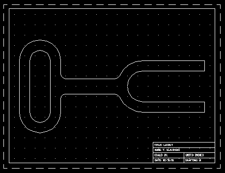
Save the drawing as "gc1" (geometric construction) inside your Unit3 folder.