Activity 2-10
[CCT, B, IL, CA,
CF]
(Guided)
Layouts & Plotting
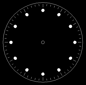
Create the following Drawing.

Each object must be located precisely. You will need to use the Polar Array tool to locate the Donuts and dashes on the watch face. If you have any difficulty in achieving the same results with the Polar Array tool, consult the AutoCAD help system or your course instructor. The Donut tool has not been discussed within this course. A short description of this tool and its application to this drawing follows:
Donut Command (Creates donuts and filled circles)
|
Use drafting settings appropriate for the dimensions of the object given below.
| Object | Dimension (mm) |
| Watch Face | Diameter - 25mm |
| Hole in Center | Diameter - 1mm |
| Filled Circles (Donuts) | Diameter - 1mm, Locate centers 10mm from center of watch face. |
| Short Dashes | Length - 0.5 mm, Start 12mm from center of watch face. |
| Long Dashes | Length - 1mm, Start 12mm from center of watch face. |
When your drawing is completed, create a layout (Scale 5:1) as indicated below.
Finished Layout
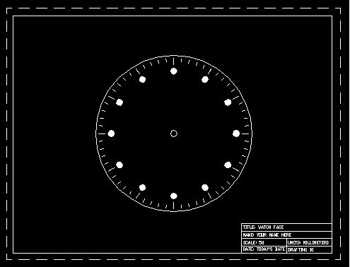
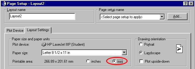
When creating the Layout, be sure to specify mm in the Layout Settings window.
You will need to scale the viewport to achieve the correct scale of 5:1 (5.000).
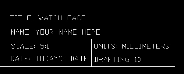
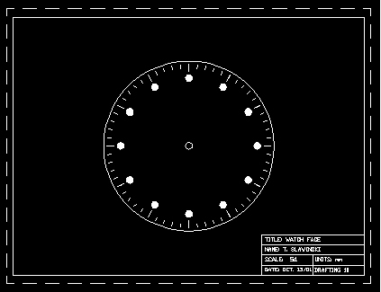
Include a Title Block with the following information.
Save the drawing as "layout" inside your Unit2 folder.
I will guide you through several portions of this drawing. The method and steps I am about to demonstrate are by no means the only way to construct this drawing. You do not need to use this help if you are comfortable in tackling this project on your own.
Start AutoCAD LT and create a new file with the following drafting settings.
Create an Object layer (default line and color values) and set the Object layer to active.
Set your snap x y spacing to 0.5 and grid spacing to 1.0. Turn your grid and snap on and then zoom in on the drawing area so that it is full screen (you can use View -> Zoom -> Extents).
Move your origin to the center of the drawing area (12.5, 12.5) and then create two circles from the origin (diameters - 25 & 1).
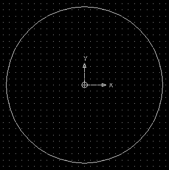
Create a short dash (0.5 units long) using the line tool at the top of the watch face (0, 12 to 0, 11.5).

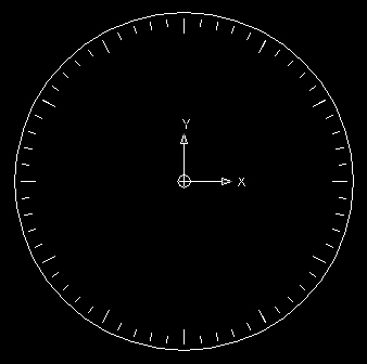
Then use the Array Tool (Polar Array) to array 60 dashes around the edge of the watch face (see below).

Next, create a long dash (1.0 units long) using the line tool at the top of the watch face (0, 12 to 0, 11).

Then use the Array Tool (Polar Array) to array 12 long dashes around the edge of the watch face (see below).
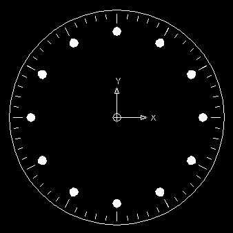
Next, create a donut using the donut command (inside diameter - 0, outside diameter - 1) with the center at 0, 10.

Then use the Array Tool (Polar Array) to array 12 donut's around the edge of the watch face (see below).
Turn your Grid display off.
Then select your Layout1 tab and then the Plot Device tab and select your printer. If you have no printer set up on your machine, you can select None.

Next, select the Layout Settings tab and adjust the layout settings to the values indicated below.

When done, click on OK. You will then see the following layout.

Next, click once on the Viewport boundary. When you see the little blue handles appear in the corner, select the corners (one at a time) and pull them towards the edge of the printing limit boundary (do not pull the viewport boundary outside of the printing limit boundary).
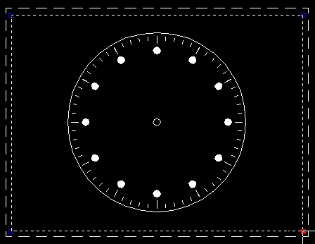
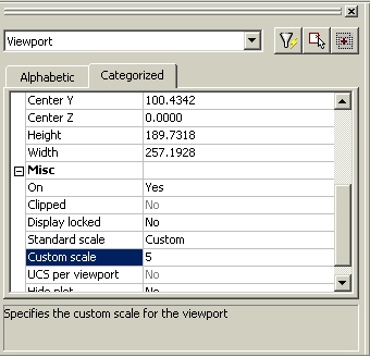
Next, you need to set the scale of the Viewport. To do so click your right mouse button anywhere inside the viewport boundary (make sure the viewport is selected - ie. the little blue handles appear in each of the four corners). Then select Properties.
You will see the Properties window appear for the viewport (see below). Scroll down the properties window until you find Custom Scale and then change the value to 5 (represent a scale of 5:1).
When done, press the Esc key and then set the origin to the bottom right corner of the Viewport boundary (see below). Make sure you snap the origin to the intersection of the Viewport boundary.
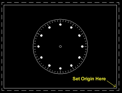
Then create a Title Block and enter the relevant data as it pertains to you. The size of the title block is not important. However, it should look balanced (ie. not too small or too large in relation to the viewport or drawing). Each row should be exactly the same height. You may need to adjust your snap x y spacing to suitable values when building the title block. In addition, you will likely need to set the text height to values appropriate to the size of each row in the title block.

Finished Layout indicated below.
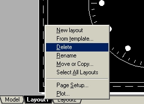
Note: if you make a mistake with your layout that you can't seem to repair, click your right mouse button on top of the layout tab and delete it. You can then create a new layout.
Save the drawing as "layout" inside your Unit2 folder.