Activity 2-4
[CA, CF, TL , IL]
Object Properties
This activity will provide you with the opportunity to practice creating layers and adjusting layer properties. You will be required to produce 1 drawing file.
Before you begin this activity, I will introduce 1 additional feature available in many CAD applications. I will show you how to change the display settings so that the background displays in black instead of white. Many CAD applications automatically default to a black background (this seems to display some line colors more effectively).
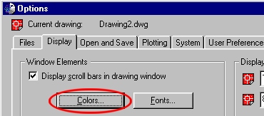
Inside AutoCAD LT, select the Tools - Options... menu item.
Select the Colors button.
Select the Color drop down list and change the color to black.
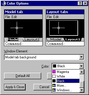
Then select Apply & Close.
Note: for the balance of this course, you may (if you prefer) create your drawing assignments in a background color of your choice. If you do change the display settings, any previous drawings opened or new drawings created in AutoCAD will display with those settings until you change it again.
Start AutoCAD 2000 LT and create a new file with the indicated drafting settings.
Create the indicated layers with the following properties:
| Layer Name | Color | Linetype |
| Object | black (or white depending on background) | continuous |
| Hidden | red | hidden |
| Center Lines | blue | center |
Symbols |
green |
continuous |
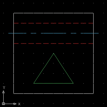
You will only need the line tool to construct this drawing. Each line object must be drawn within its respective layer. The placement of each object must be precise. Use the origin (0, 0) and grid (each dot represents 0.5 units) indicated below to locate the placement of each object. I suggest setting your snap settings to 0.25 units.
Save as "layers" inside your Unit2 folder.