Activity 2-8
[NUM, CA, IL, CCT, B]
(Guided)
User Coordinate System (UCS)
This activity will provide you with the opportunity to practice using the UCS tools discussed to create drawings.
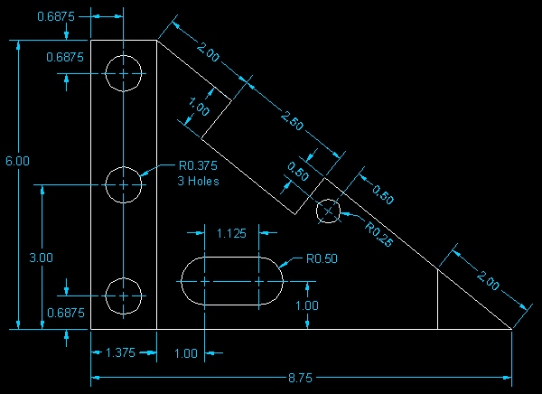
Start AutoCAD 2000 LT and create a new file. Use drafting settings appropriate for the drawing indicated below.
Use the dimensions given to locate and place the various drawing objects. Do not draw any dimensions. To create this drawing accurately, you will be required to move and rotate your UCS several times. You will also be required to use object snaps throughout the drawing. Each object can be located exactly using the tools you've learned so far. Be precise!

When you are done, your drawing should look as follows:
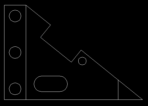
Save the drawing as "ucs" inside your Unit2 folder.
As stated previously, I will guide you through several portions of this drawing. The method and steps I am about to demonstrate are by no means the only way to construct this drawing. You do not need to use this help if you are comfortable in tackling this project on your own.
Start AutoCAD LT and create a new file with the following drafting settings.
Create an Object layer (default line and color values) and set the Object layer to active.
Set your snap settings to 0.25. You can leave the grid setting at the default 0.5. Turn your grid and snap on and then zoom in on the drawing area so that it is full screen (you can use View -> Zoom -> Extents).
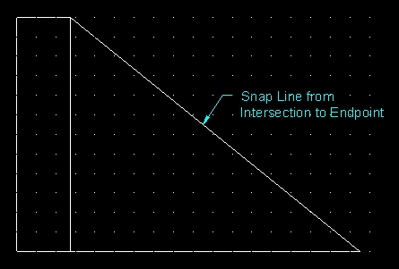
Draw the following lines (using the dimensions provided above) using the Line tool:
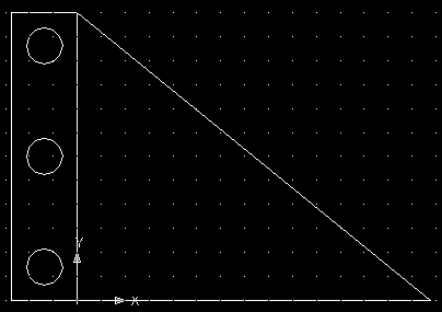
Snap your origin to the following intersection and draw the indicated circle (center at (0.6875, 0.6875) with radius 0.375).

Snap your origin to the top left intersection of the shape and draw the indicated circle (center at (0.6875, -0.6875) with radius 0.375).

Snap your origin to the midpoint of the left edge of the object and draw the indicated circle (center at (0.6875, 0) with radius 0.375).

Snap your origin to the following intersection:
From this location, move your origin one more time to position (1, 1).

Using your Arc Tool, draw the following arc (with radius 0.5).

Move your origin 1.125 units to the right and then draw the other arc.
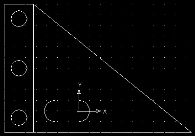
Then connect the arcs using the Line Tool (snap from endpoint to endpoint).
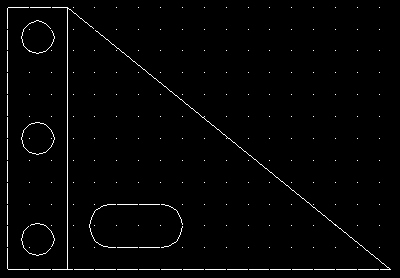
Next, use your Object UCS tool to rotate your grid along the sloped line. Be sure the origin is set to the intersection indicated below.

Then move your origin 2 units along the x axis (2, 0) using the Origin UCS tool.
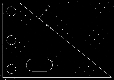
Then draw the lines indicated below.

Next, move your origin to the following intersection and draw the indicated circle (center at (0.5, -0.5) with radius 0.25).
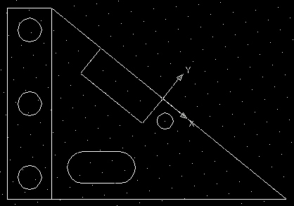
Next, move your origin to the following intersection and then draw a line from (-2, 0) and connect it to the base of the object (Snap to Perpendicular).

Next, delete the sloped line (see below).
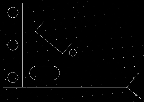
Then replace the deleted line with the two lines indicated below (be sure to use your snaps when creating the lines).
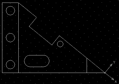
If you wish, you can return your UCS position to normal (using the World UCS tool).

Save the drawing as "ucs" inside your Unit2 folder.