
Units: inches
Activity 5 - 1
(Guided)
[CF, CA, TL, T, COM]
Create a Cabinet Oblique drawing of the following object. In addition, create a layout (scale 1:1) with title block.

Units: inches
To help ease your transition into oblique projections, I will guide you through this first drawing.
The direction of projection and the receding angle is a matter of personal preference. However, once a direction of projection and receding angle is chosen, you cannot change it. In this activity, we will project to the top-right.
The receding axis angle is typically one of 30, 45, or 60 degrees. We will project at an angle of 30 degrees.
Given that we are creating a Cabinet Oblique, the receding line (depth) is exactly 1/2 the true length.
Create a new drawing from Scratch and select English units (feet and inches).
We do not to need to worry about spacing given that we will only be creating one drawing. Setting the drawing limits is arbitrary as well. We will dispense with adjusting these values.
To be consistent with my drafting settings, set your Snap to 0.2 and your Grid to 1.0 (Tools - Drafting Settings).
As mentioned in the previous section, the front view (vertical & horizontal axis) is parallel to the frontal plane and the other two faces are oblique (receding).
In oblique drawings, the most forward portion of the front view is usually drawn first. In the image below, the forward most section of the frontal plane is outlined. The portions crossed-out belong to a deeper portion of the front plane and will be drawn later.

Set your origin to a location convenient for you and then draw the most forward portion of the frontal plane using the dimensions provided. Be precise. The start and end of the angled lines can be derived exactly. Use your origin UCS tools and coordinate system.

The most frontal plane is now completed. We must now begin moving back deeper into the drawing.
Determining which plane to draw next is often a matter of personal preference. In the case of this drawing, the most frontal plane is identical to the plane furthest back. So, it makes sense to duplicate the portion of the drawing just created and then place the duplicate at the correct depth (along the receding axis).
Let's now draw the rear-most plane.
Set your origin to the intersection indicated below (be precise - use your snaps if necessary).

Select the Copy tool and drag a box around all the lines drawn and then press the Enter key.

The command line will then ask for a base point. Select the current origin as your base point.
Then, the command line will ask for a displacement. We wish to recede at an angle of 30 degrees and at a depth of 1 (1/2 the actual depth).
Enter the displacement location relative to the base point by typing 1<30 on the command line (see below).

Then press the Enter key. You should see the following:

Next, insert the receding lines that connect the front and rear planes (be sure to use your snap tool).

Next, trim away any lines that would be hidden from view.

Let's now move back up to the most frontal plane and start filling in some of the missing detail.
The next plane we will draw is outlined in the image below. The depth of the next plane is circled in red.

Set your origin to the intersection indicated below.

Draw a receding line (length - .1, angle 30 degrees) from the origin. Remember that in cabinet oblique drawings, receding line length is 1/2 true size. When drawing the receding line, I suggest selecting your origin (0, 0) as the first point and then specify the second point relative to the origin (0.1<30) using manual polar coordinate entry.

Copy the line just drawn and place a duplicate in the locations indicated below. Be sure to use your snaps.

Next, draw the vertical line indicated below (length - 0.4 true height).

Then duplicate the line in the other two locations.

Next, connect the lines to finish the front and oblique faces.
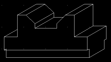
You will then need to trim away lines hidden from view (see below). You will likely need to zoom in to perform this task.
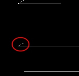 Before |
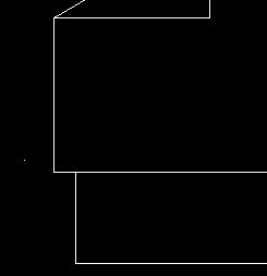 After |
The next plane we will draw is indicated by arrows in the image below. The dimensions needed for the next plane are circled.
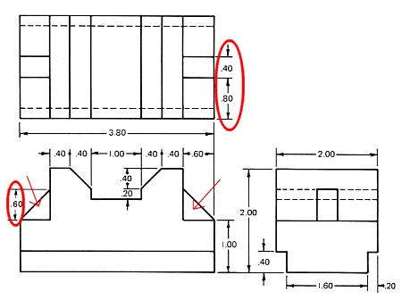
We will need a reference point to measure from in order to draw the triangular features.
Set the following location as your origin.
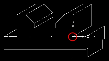
Then re-locate the origin to the location where the first triangle is to be drawn. Remember that the start location of the first triangle is 1/2 the true distance from the front plane. Use polar coordinates to locate the new origin (0.4<30).
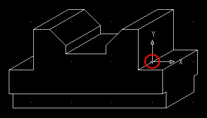
Then draw the first triangle (true size).
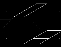
Copy and place a duplicate of the triangle 0.2 units and 30 degrees away from the original (0.2<30).
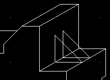
Then insert any lines needed to complete the detail and trim away any hidden features.
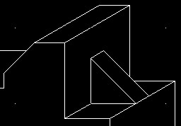
Let's now do the other side.
Set your origin to the following location.
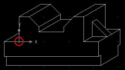
Relocate your origin one more time to the location where the triangle is to be drawn. Again, the start location of the triangle is 1/2 the true distance from the front plane. Use polar coordinates to locate the new origin (0.4<30).
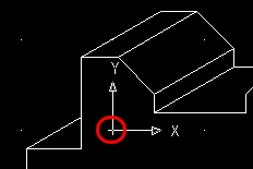
Then draw the triangle true size.
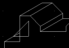
Finally, trim away any hidden detail.
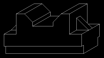
Your Cabinet Oblique Projection is now complete.
Your final step is to create a layout, complete with title block.
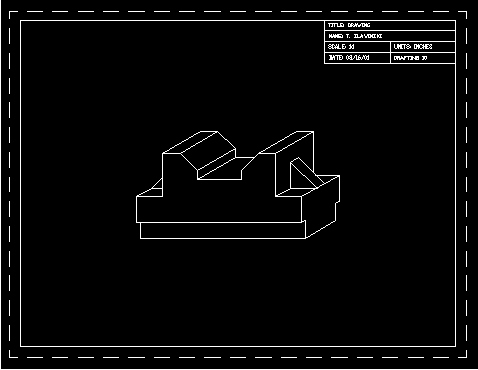
Save the drawing as "pd1" (pictorial drawing) inside your Unit5 folder.