
Units: mm
Activity 5 - 3
(Guided)
[COM, TL, T, CA, CF]
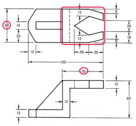
Create an Isometric drawing of the following object. In addition, create a layout (using an appropriate scale) and title block. When the drawing is done, you do not need to scale the isometric drawing down to 80%.

Units: mm
To help ease your transition into Isometric drawings, I will guide you through this first drawing.
Create a new drawing from Scratch and select Metric units (mm).
We do not to need to worry about spacing given that we will only be creating one drawing. Setting the drawing limits is arbitrary as well. We will dispense with adjusting these values.
To be consistent with my drafting settings, set your Snap to 10 and your Grid to 10 (Tools - Drafting Settings).
Create a new layer and call it Object. Accept the default settings for this layer.
Change the current layer to Object.
I will introduce a few new techniques that will help you layout isometric drawings. With complex objects such as the object you are about to draw. It is necessary to break the drawing up into sections. The section you choose to draw first is arbitrary. We will begin by drawing the section outlined in red below. The overall length and width of the section indicated are also circled in red.
Start by setting your Isometric Snap to On (Tools - Drafting Settings).
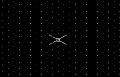
Then set the Isometric snap mode to Top (see below). Remember that the F5 key can be used to toggle between the three modes (Left, Right, and Top).
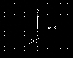
Set Your Origin UCS to somewhere in the middle of your drawing area (see below).
Your coordinate display should be set to display relative coordinates.
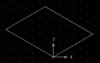
We are now ready to begin drawing. When creating isometric detail that is complex in shape, it is easiest to place the detail inside of a rectangular isometric bounding box. The bounding box must be exactly the same size (length and width) as the detail being drawn. Let us now create the bounding box for the detail indicated below.
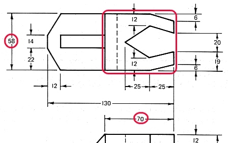
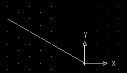
Select the Line tool and indicate the first point (0, 0). Set the second point to the relative coordinate of 70<150 and then press Enter. You can use your grid as a guide. Press the Esc key to get out of Line mode.
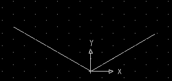
Select the Line tool again and indicate the first point (0, 0). Set the second point to the relative coordinate of 58<30 and then press Enter. Press the Esc key to get out of Line mode.
Finish the isometric bounding box by duplicating each of the two existing lines and snapping them into their correct location (see below).
The bounding box created above will house all the detail for this section. We are now going to mark the locations of important intersections needed to construct the detail for this section. To do this we will be using the Point tool.
Set your Point tool to a shape of your choice (that is easily recognizable) using Format - Point Style.
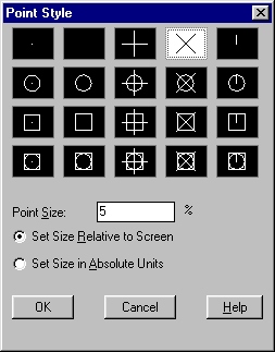
There are several methods that can be used to locate the points for important intersections. The method I am about to demonstrate will require the moving of the current origin UCS. Let's now mark the following locations on our bounding box.
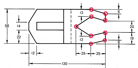
When placing points, pick any corner of your bounding box to be your origin. Then using the dimensions indicated above, place as many points as you can easily define in the box. When done, move your origin to a new location and place more points.
I will demonstrate the first few points starting in the lower right corner of the bounding box.
Make sure your origin is set to the following location.
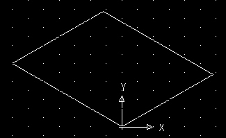
Using your Point tool place points at the following coordinates:
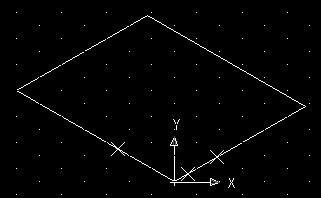
Then move your origin to other convenient locations and finish placing the rest of the points. You will likely need to snap your origin to another point or a midpoint of a line to finish placing all the points. Remember - be precise.
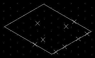
All Points Located
Next, connect the points using your line tool (see below). Be sure to use the Snap to Node when creating the lines.
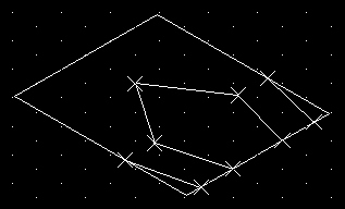
When done, you can remove the points and delete any unwanted lines (see below).
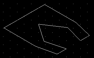
Let's now duplicate the above detail and place the duplicate exactly 12 units below the existing one.
Set your origin to the following intersection.
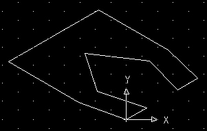
Select the Copy tool and then select all of the existing lines and then press the Enter key.
When the command line asks for a base point, specify the same intersection as the origin using your mouse & snap or by entering (0, 0) on the command line.
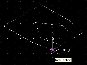
When the command line asks for the first point as displacement, enter the absolute coordinates 12<270.
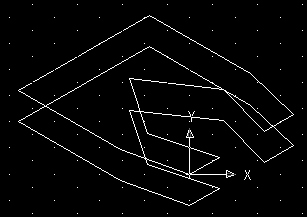
Copy Properly Placed
Next, connect the related intersections using the Line tool and then delete/trim any detail hidden from view.
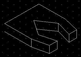
Completed Top Section
Using the existing detail, we can now move on to another portion of the object.
Change your Isometric Snap mode to Left and set the following intersection as your origin.
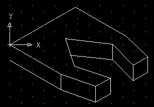
We will now complete the following detail indicated in red. The dimensions we will require are also circled in red.
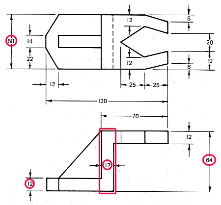
Start by creating a line exactly 52 (64-12) units long and extending downwards vertically from the origin (52<270).
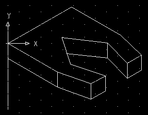
Move your origin to the following location.
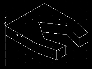
Place a point 12 units to the right of the origin along the isometric axis (12<-30).
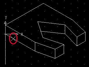
Draw a line starting at the point and extending down vertically exactly 52 units long (@52<270).
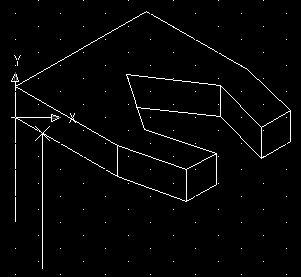
Change to Right mode and draw a line from the endpoint of the previous line extending to the right (along the isometric axis) exactly 58 units long (@58<30).
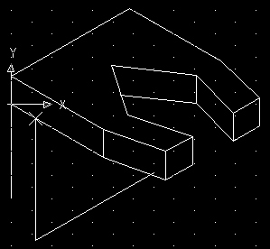
From the endpoint of that line, draw a line extending vertically up exactly 52 units long (@52<90).
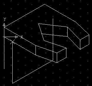
Then trim away any line sections hidden from view.
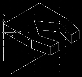
You can also trim away the portion of the line to the left of the point (placed earlier) and then remove the point (see below).
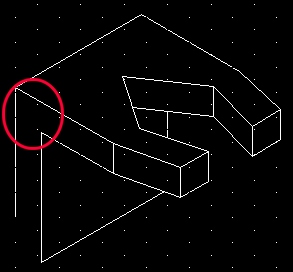
Our next step is to build a bounding box that will contain the lower portion of the object.
Set your origin to the following intersection.
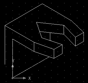
We will now complete the following detail indicated in red. The dimensions we will require are also circled in red.
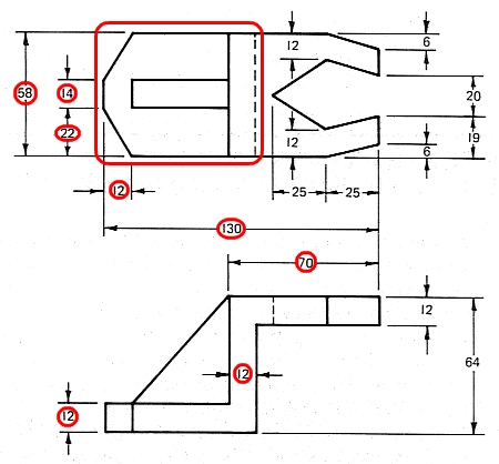
From the dimensions given above, we can extrapolate mathematically the size of the bounding box needed (from the previously defined origin) - 72 x 58.
Change your Isometric mode to Top.
Draw a line from the origin (0, 0) extending to the left (along the isometric axis) exactly 72 units long (72<150).
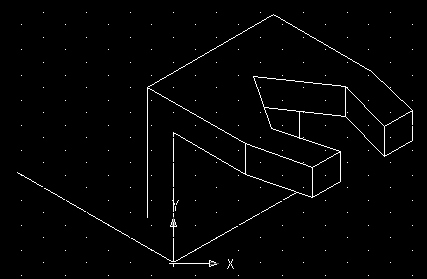
Move your origin to the endpoint of the line just drawn and create another line from the endpoint extending to the right (along the isometric axis) exactly 58 units long (58<30).
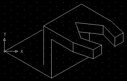
Copy the line indicated below and snap the duplicate to the endpoint of the line just drawn.
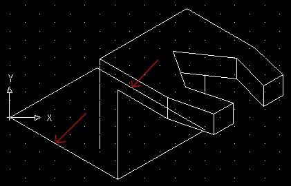
Then place points at the important intersections (i.e. 12 & 22 units from the corners).
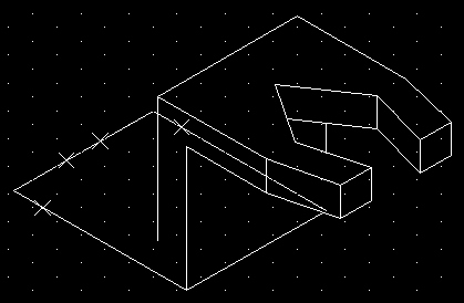
Then use the Line tool to connect the points and then delete the points and trim the lines.
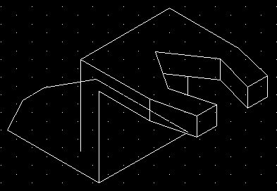
Copy the lower section and place the duplicate 12 units above the section just created.
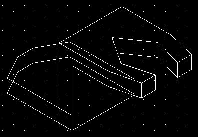
Then connect any necessary intersections and trim away any lines hidden from view.
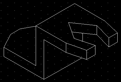
Let's now build the feature indicated below.
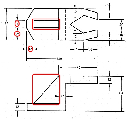
Place your origin at each of the following intersections and then place your reference points (22<30 & 36<30 from each origin).
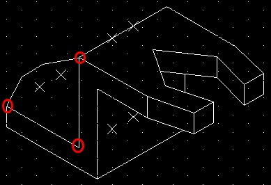
Then connect the relevant points using the Line tool. Not all the points need to be connected (some of the lines are hidden from view). Often it does not become evident which lines are needed until all the points are placed.
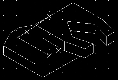
Then trim away any lines hidden from view. You can also delete the points used for construction purposes.
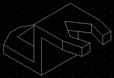
Completed Isometric View
The last step is to create the layout with title block.
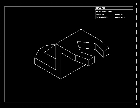
Save the drawing as "pd3" (pictorial drawing) inside your Unit5 folder.