Oblique Projection
[CF, TL, COM, CW]
In oblique projections the front view is drawn true size, and the receding surfaces are drawn on an angle to give it a pictorial appearance.This form of projection has the advantage of showing one face (the front face) of the object without distortion. Generally, the face with the greatest detail faces the front.
There are two types of oblique projection used in engineering design.
Cavalier Oblique
In cavalier oblique drawings, all lines (including receding lines) are made to their true length.
Cabinet Oblique
In cabinet oblique drawings, the receding lines are shortened by one-half their true length to compensate for distortion and to approximate more closely what the human eye would see. It is for this reason that cabinet oblique drawings are the most used form of oblique drawings.

Typical Angles of Projection
In oblique drawings, the three axes of projection are vertical, horizontal, and receding. The front view (vertical & horizontal axis) is parallel to the frontal plane and the other two faces are oblique (receding). The direction of projection can be top-left, top-right, bottom-left, or bottom-right. The receding axis is typically drawn at 60, 45, or 30 degrees.
Top Left
Top Right

Bottom Left
Bottom Right
Practice Activity
[IL, B, CCT, CF]
I strongly suggest that you open AutoCAD LT and try these practice activities before tackling the assigned activities for this unit.
We will be using English units (inches) in all the samples below.
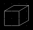
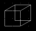
Let's assume we wish to create an Oblique projection of the following object.
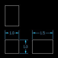
When the front and rear faces are identical (as in the object above), there are two approaches to creating the oblique projection. I will introduce both methods.
Method 1
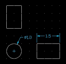
In the drawing above, there are only two planes of depth (front and back). Generally the frontal plane is drawn first.
Then draw the receding lines (true length for cavalier oblique and 1/2 length for cabinet oblique drawings).
| The start point of each line is snapped to the intersection. The end point is entered using relative polar coordinates @1.5<30 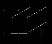 Cavalier |
The start point of each line is snapped to the intersection. The end point is entered using relative polar coordinates @0.75<30 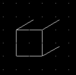 Cabinet |
Then connect the appropriate lines on the back plane.
 Cavalier |
 Cabinet |
Method 2
Draw the front plane.
If the back plane is identical to the front plane, then copy and place the duplicate at the appropriate angle and distance from the front plane.
| Use the copy command. Use any intersection as a base point and then place the duplicate using relative polar coordinates @1.5<30 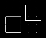 Cavalier |
Use the copy command. Use any intersection as a base point and then place the duplicate using relative polar coordinates @0.75<30 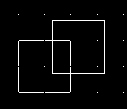 Cabinet |
Then connect the two planes with the receding lines.
 Cavalier |
 Cabinet |
Then trim away any hidden details.
Cavalier |
Cabinet |
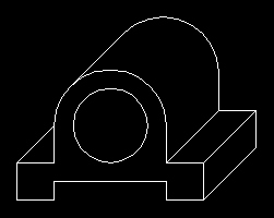
Circular Features
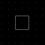
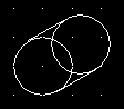
Let's assume we wish to create an Oblique projection of the following object.
In this case, you need to construct the front and rear planes first.
| Use the copy command. Use the center as a base point and then place the duplicate using relative polar coordinates @1.5<30 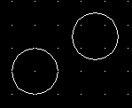 Cavalier |
Use the copy command. Use the center as a base point and then place the duplicate using relative polar coordinates @0.75<30 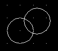 Cabinet |
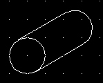
Then snap receding tangent lines connecting the two planes.
 Cavalier |
 Cabinet |
Then trim away any hidden details.
 Cavalier |
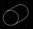 Cabinet |