Axonometric Projections
[COM, TL, CA,
CF, CW]
Axonometric projection is the projection of an object onto a drawing surface with the object positioned so that it appears three-dimensional. There are three types of axonometric projection. However, in this course, we will focus on the Isometric method of projection.
Consider the following object:
Isometric drawing of the above object:

The word isometric means "having equality of measure". This means that the object is placed with its major edges at equal angles with the drawing plane.
Isometric Cube

Three Equal Angles
In isometric drawings, the vertical edges are drawn vertically on the drawing surface and the horizontal surfaces are rotated 30 degrees.

When creating isometric drawings manually (using pencil and paper), all lines are 80% of their true length. The drafter must manually convert each line segment before drawing the line.
Using CAD, the isometric drawing is generally drawn true size and then it is scaled down using the scale tool.
| Above object drawn using true-size lines  Appears disproportionately large |
Above object drawn using true-size lines and then scaled to 80% actual size. 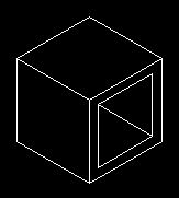 More accurately depicts size of actual object |
Practice Activity
( IL, B, T )
I strongly suggest that you open AutoCAD LT and try these practice activities before tackling the assigned activities for this unit.
We will be using English units (inches) in all the samples below.
AutoCAD LT contains several tools used specifically in creating isometric drawings. The most important of which is the isometric snap mode.
From your menu, select the Tools - Drafting Settings item. Make sure Isometric snap is selected (see below).

You will notice that your grid pattern and mouse cursor change shape.

Once you set the snap style to Isometric, you can work on any of three planes, each with an associated pair of axes:
|
|
Choosing one of the three isometric planes causes Ortho and the crosshairs to be aligned along the corresponding isometric axes. For example, when Ortho is on, the points you specify align along the simulated plane you are drawing on. Therefore, you can draw the top plane, switch to the left plane to draw another side, and switch to the right plane to complete the drawing.

To toggle between Left, Right, and Top modes, use the F5 key. Notice how the cursor changes shape to align with the axis.
 Left Mode |
 Top Mode |
 Right Mode |
Let's assume we wish to create an isometric drawing of the following solid block:
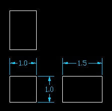
Orthographic drawing

Finished Isometric
To do this practice activity, use the default grid (0.5) and snap (0.5) settings. Make sure your Isometric snap is on. For this first exercise, we will be using the isometric grid and snap settings to draw the isometric.
Lets start with the Left mode. Press the F5 key until your cursor looks as follows:

Make sure that your coordinate display is set to indicate relative polar coordinates. To do this, select any drawing tool (such as line) and then click anywhere on your drawing area to indicate the first point.
While you are still in drawing mode, click your right mouse button on top of the coordinate display.

If your coordinate display is set to relative, then the word Relative will appear grayed out.
Press the Esc key to get out of drawing mode.
Let's begin drawing. Make sure your grid and snap are turned on.
Select the Line tool and click on any point somewhere in the middle of your drawing area. Then pull a line down exactly 1 unit (use the coordinate display).

Then pull a line exactly 1.5 units to the left (along the isometric axis). Use the shape of your mouse cursor as an aid to find the axis.

Then pull a line exactly 1 unit up.

Then pull a line back to where you started and press the Enter key.

Next, switch your isometric snap (F5) to Right and then draw the right plane of the object.

Then, switch your isometric snap to Top and then finish drawing the object.

In the simple example above, all of the points happened to fall neatly on the grid. In most real life design situations, this will not always be the case. Under those circumstances, you will need to enter coordinates manually. This will be demonstrated in the first isometric guided activity later on.
I will now demonstrate drawing circular isometric features. Take, for example, the following object.
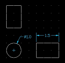
Orthographic drawing
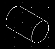
Finished Isometric
Many CAD applications have a feature that allows the drawing of isometric circles.
We will start by drawing the isometric circle first.
Switch to the Right isometric plane.
Then type "ellipse" on the command line
and then press the Enter key or press the ellipse button ![]() on the drawing toolbar.
on the drawing toolbar.

The command line then asks you to select from one of three options. Enter I or i for Isocircle.
The command line will then ask you to specify the center of the Isocircle. Select a point somewhere in the middle of your drawing area using your mouse.
![]()
Then specify the radius of the isocircle (0.5) and then press the Enter key. You can also specify the diameter by entering d or D on the command line and then entering the diameter.
![]()

Isocircle
Next, using the Origin UCS tool, set the current origin to the center of the isocircle (snap to center).

Next, draw another isocircle 1.5 units from the origin and at an angle of 150 degrees.
Use the same steps indicated above. When the command line asks for the center of the Isocircle, enter the absolute coordinates of 1.5<150.

Next, connect the two isocircles using lines (snap to quadrant).

Then, trim away the hidden portion of the second isocircle.